

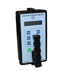

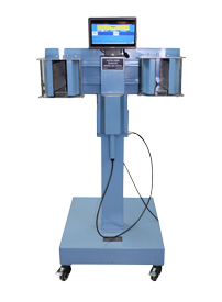
On-line Gamma Monitor [TYPE : OG724]
Technical Data

Online Gamma Ray Monitor type OG724, manufactured by NUCLEONIX SYSTEMS employs state-of-art microcontroller based design and is primarily meant to serve as a Gamma Zone Monitor to indicate dose rates and give alarm, visual and aural, once the dose rates exceed the preset level fixed by the user. Also relays will be activated on alarm.
This unit will be useful for monitoring Gamma countrate activity levels in certain process systems like Process cooling Water system, Steam Header land master system efficient discharge lines, etc., It comprises of a wall mountable electronic unit with displays and controls and an extendable detector assembly.
This unit indicates the dose rate digitally on a 4 x 7 segment LED display. Each of the annunciator windows for NORMAL and ACTIVE conditions has LED array. Once alarm triggers ACTIVE window starts blinking.
Unit can be programmed / configured using front panel keypad which can be deactivated after completion of programming. Configuring the unit namely setting preset level, setting reset mode – AUTO/MANUAL etc are achieved by this keypad.
Unit also performs self-diagnostics for HV failure, pulse processing electronics failure & detectors failure on power up.
Alarm acknowledge and reset pins are provided on the circular I/O connector for remote acknowledge & reset.
Features
Specifications
| Radiation to be detected : | Gamma Radiation. |
|---|---|
| Range : | 0 to 500000 CPM / 0 to 20000 CPS Range / 0 to 500000 Bq. Unit and range are programmable. |
| Detector : | NaI Scintillation detector 1½ ” dia x 1½ ” thick with Photomultiplier tube. |
| Accuracy : | +/ – 10% Full scale |
| EHT : | 300V to 1500V DC adjustable with output current of 500 A max. |
| Display : | Alpha numeric LED display. Data in engg. Units. Unit configurable. Diagnostic information and messages also shall be displayed |
| Amplifier specifications : | Input impedance- > 1 K Ohm
Gain – Max. 100, adjustable with 10 turn potentiometer. Time constant – Differentiation: 1 µsec & Integration: 1 µsec. |
| Single channel Analyzer : | Operating mode œ Window mode or Integral mode, selectable. Base line- 0.05 to 10 V, continuously adjustable by 10 turn pot Window width – 0 to 2 V, continuously adjustable by 10 turn pot. |
| Efficiency calculation : | The instrument shall have facility to calculate the efficiency of the detector and convert the counts into Bq. |
| Overload : | Senses overload above full scale of the measurement unit & indicates on display “OL”. |
| Over-range : | Senses if the radiation field being measured has exceeded the full scale of the instrument and upto 999999 CPM / 30000 CPS / 999999 Bq depending upon the unit and displays “OFl” . |
| Recorder output : | 4 to 20 mA, with 600 ohm load |
| Recorder output stability : | a) Non-linearity : Max = 0.025% of Span b) Offset current (Io=4mA):Max = 0.0005% of Span / oC c) Span Error (Io=20mA) : Max = 0.005% of Span / oC |
| Timer Constant : | First reading on Power ON within 5 secs. Normal (Slow) : 10 sec to 0.5 sec automatically varying inversely with the radiation level. Abrupt detection : Update the current reading within 2 sec and return to normal mode. |
| Calibration Accuracy : | +/- 10% through out the range. |
| Instrument “ON” Indication : | Large Area Green LED Lamp. This will indicate the Normal condition also. |
| Alarm range : | 1 to 20000 CPS / 1 to 500000 CPM / 1 to 500000 Bq The alarm level setting shall be carried out Keypad / Hand held configurator / PC. |
| Alarm Indication : | a) Red (LED) flashing large area window display b) Loud audio tone with frequency 2000 Hz & 1000 Hz |
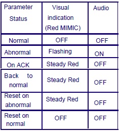
Alarm annunciation scheme
As tabulated below :
Instrument Controls :
a) Acknowledgement switch for muting audio
b) Reset switch for resetting the Alarm indication and alarm relay.
c) Power ON/OFF switch with Power ON indication
d) EHT ON/OFF (this switch is inside the cabinet).
Instrument Fault indication :
a) EHT failure: Visual alarm with flashing RED LED indication & “Eht” message on display
b) Detector failure: Visual alarm with flashing red LED & “d-FL” message on display.
c) Microprocessor / microcontroller failure: Visual alarm with flashing green lamp.
d) Fault indications are cleared automatically if normal status is resumed.
Detector Housing:
a) The Detector shall be located external to the Monitor. It shall be provided with an adjustable SS strap for fixing on the pipe line. Alternatively, the detector assembly shall be fitted in a SS well fabricated on the pipe line.
b) It shall be housed in a suitable, air-tight S.S. shell with built-in pre-amplifier to drive upto 50 mtrs long cable.
c) The detector assembly shall be mounted on the pipe line with 20 mm lead shield assembly to reduce the background radiation.
d) The instrument shall be provided with 30 mtr cable between detector and the monitor.
e) The detector housing shall qualify minimum industrial protection Class IP-54.
f) The monitor shall also have a bracket on the side for fixing the detector assembly.
g) Provision to connect the detector with short cable also hall be available.
Monitor Enclosure:
a) Vapor-tight, rugged & elegant.b) The door is provided with lock and key arrangement
c) The enclosure is designed to qualify minimum industrial protection Class IP-65.
d) Decorative with visual aesthetics, prominent alarm display and good readability.
Mounting :
The Detector shall be mounted on the pipe line or shall be fitted in a SS well fabricated on the pipe line. The mounting arrangement shall be designed to achieve the maximum sensitivity. The complete arrangement for mounting including the SS well shall be part of the supply.
The Monitor shall be wall-mountable type. Brackets for the same shall be supplied along with the instrument.
Remote /External Console :
a) 4 – 20 mA linear proportional to full scale display output. Current output will be able to drive load of 600 ohms. Output circuitry will be able to drive 200 mtrs.of twisted pair of wires.
b) Two sets of potential free contacts of Alarm relay (Change over). Contact rating 3 Amp at 250 VAC. The relay is energized on normal condition and de-energised under alarm condition.
c) Remote alarm acknowledgement and reset signals for the field instruments (Normally open contact).
d) Indication of instrument fault condition (detector, EHT & LV supplies failure), overflow & overload condition by up-scale 4-20 mA. (22.5 mA).
e) All these signals are terminated on a 17 pin socket (Allied Connectors). The corresponding mating plug with 5 mtr cable will be supplied with the monitor.
f) RJ45 connector for Ethernet port
g) RS-485 serial port (optional). This is provided, on a pair of D-type connectors (male & female).
Computer Interface :
The monitor shall have a Ethernet 10/100 Mbps port for interfacing with a remote IBM PC-compatible computer.
The features supported by Ethernet port are given below.
The PC and the monitor shall operate in a host-slave configuration and the software protocol will be MODBUS/TCP.• The PC as the host shall give commands and send queries. The monitor will carry out various functions in response to the queries.
The firmware of the monitor shall be able to send the instrument data like instrument ID, instrument type, input range, display range, alarm settings, alarm status, current reading, diagnostic status of EHT/GM tube etc. to the Host PC on demand.
The firmware shall be able to receive commands from Host PC and carry out the setting of different parameters like instrument ID, instrument type, input range, display range, alarm settings, Ack, Reset, instrument address etc.c. The instrument is provided with 10 mtr cable between Smart Probe and themonitor.
RS485 (Optional)
This monitor has a RS-485 Serial Communication port for interfacing with a PC. The PC and the monitor operate in a host-slave configuration in a multi-drop network through this interface. The PC, as the host will give commands and send queries. The monitor will carry the various functions as per the required information in response to the queries.
The firmware of the monitor sends the instrument data like Instrument ID, Instrument type, Input range, Display range, alarm settings, alarm status, current reading, diagnostic status of EHT/GM tube etc. to the Host PC on demand. The firmware receives commands from Host PC and carries out the setting of different parameters like Instrument ID, Instrument type, Input range, Display range, alarm settings, Ack, Reset, EHT setting, Instrument address etc. The configuration settings are password protected and the password is user defined.
The detailed specifications for the interface are as follows:-
Type : RS-485 Multi-drop Serial Communication Port, Half Duplex Bi-directional communication.
Character Format : ASCII
Protocol : Modbus/RTU
Bit Rate : User configurable to 9600 or 19200 bits per sec.
Address : User configurable from 0 to 255.
Connector : 9-pin D-type connectors (2 connectors connected in parallel for daisy chaining a number of instruments). The mating connectors with cover are supplied.
Self Diagnostics :
The monitor will have built-in self diagnostics. On being powered it will perform tests to ensure that all components and sub systems are functioning properly. It will check for the Power supply, High Voltage Supply, Detector and pulse processing electronics.
The firmware should not halt monitoring / data acquisition function any time. The firmware shall be designed for high reliability and availability. Test points shall be provided for checking the EHT voltage and for connecting external input pulse signals.
Input Power :
230VAC +/-10%, 50Hz +/- 3 Hz, single phase supply. Power ON/OFF switch shall be provided with an indicator LED. Spike suppressor and line filter shall be provided.
Environment :
The instrument will be able to withstand temperature upto 50o C and relative humidity upto 90% in radiation areas.
The instrument enclosure and detector assembly shall comply with IP-54.Electronic units shall withstand cumulative radiation dose of 10000 Rad. (30 years of operation).
Instrument Trolley :
a) The Instrument trolley shall be made of M.S. and shall be provided with brackets for mounting the instrument and detector.
b) The trolley shall be provided with castor wheels with locks / breaks.
c) The trolley shall be powder coated with Siemens Grey colour.
d) One Mains supply board with required sockets, indicators and switches / MCBs shall be provided on the trolley.
