


Description
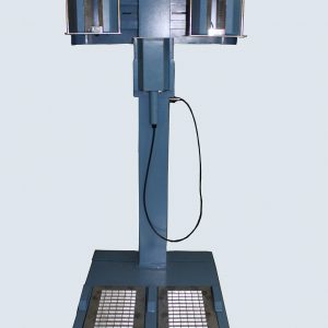
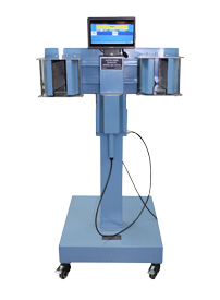
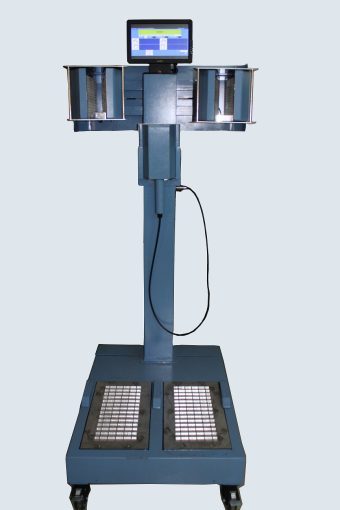
Alpha Hand, Foot & Clothing Monitor NXG_HFC1_A manufactured by NUCLEONIX SYSTEMS primarily serve as a personnel monitoring system for checking the contamination of hands, foot & clothing of radiation worker / technicians working in Nuclear Power Plants, reactors, Radiochemical plants and other similar installations.
This instrument has been developed using state of art SBC working on WinCE. GUI & multi-lingual user interface & corresponding voice messages are facilitated by a color TFT monitor with integrated speakers.
Guidance to the user during monitoring in the form of color graphic monitor for left / right hand / foot & status indications during monitoring & at the end of monitoring are a standard feature of this instrument.
Advanced fault diagnostic features facilitate the user to diagnose the problem easily. Also provision for faulty channel bypassing feature has been provided. USB & Ethernet communication for data downloading to PC.
Each Hand & Foot detector assembly shown is modular in construction facilitating easy maintenance in case of problems.
Features
Specifications
The Alpha Hand and clothing monitor shall comprise a set of detectors and an electronic unit.
DETECTORS:
Hand probes:
| a) Hand probes: | Number of monitoring channels: 4 (Right hand 1 & 2, Left hand 1 & 2). Detector Type: 235x150mm Zns(Ag)scintillator based detection unit. Detection Efficiency: >>25 % overall forAm-241. Probe Construction:Each channelshall have a 235x150mm Zns(Ag)scintillation detectors. They are fittedin the instrument so that they can bedetached easily for maintenance. Sensitive Area. > 300 sq. cm. Protection Grill: The whole detector assembly shall be protected by a suitable thin metallic grill. Detector dimensions and performance shall conform to IEC61098 specifications |
|---|---|
| b) Clothing probe: | Number of monitoring channels: 2(Right foot 1 &, Left foot 2). Detector Type:347x150mm Zns(Ag)scintillator based detection unit. Detection Efficiency:>20 % overall forAM 241. Probe Construction: Each channelshall have a 347x150mm Zns(Ag)scintillation detectors. They are fittedin the instrument so that they can bedetached easily for maintenance. Sensitive Area:>300 Sq.cm. Protection Grill:The whole detectorassembly shall be protected by asuitable thin metallic grill.Detectordimensions and performanceshall conform to IEC 61098specifications |
| b) Clothing probe: | Number of monitoring channels: one. Detector Type:175x125mm Zns(Ag) scintillator. Detection Efficiency:> 25% overall forplastic scintillation detector assemblywith Am-241. Probe Construction:Hand-held type. It shall be placed on a holder with micro-switch assembly on the side of the monitor. On lifting the detector, the monitoring shall be started. |
High Voltage, Pulse Amplifier and Data Acquisition Unit:
This unit essentially comprises of High Voltage module, 7 channel Pulse Amplifier section, FPGA based Data acquisition board and State of Art Single Board Computer unit. DC Voltages required to bias the Electronics are generated by DC-DC convertors located on this board. Signals to/from all PMTs are routed to this unit.
Switch Mode power Supplies unit:
An AC-DC converter +24V output . It is also provided with a line filter & other EMC suppression components.
Switch Mode power Supplies unit:
An AC-DC converter along with switching regulators generates the necessary LV voltages of +24V, +12V & +5V respectively to power the electronic sub-systems. It is also provided with a line filter & other EMC suppression components.
7 Channel Pre-amplifier section:
This unit comprises of 7 individual pre- amplifier used for connecting the –ve tail pulses to TTL coming from each of the scintillation detectors. HV bias to the scintillation detectors is fed through the preamplifier unit.
Counting Range :
Timing range :
Pre-settable from 1 to 99 seconds in 1 sec steps for COUNTS, Bq/cm2, CPS or CPM modes for Hand and Foot monitoring. Time constant for checking the Clothing monitoring is 5 seconds with display being refreshed every second.
Counting Range :
HUMAN MACHINE INTERFACE:
Indications & controls:
| Mains switch | The mains switch is provided inside the cabinet of the monitor. |
|---|---|
| Optical sensor | The monitor shall be provided with optical sensors inside the detector cavities for sensing personnel and initializing the counting automatically. | Visual alarm | Each channel color visual mimic indication is provided on the colour LCD TFT display. |
| Audio Alarm | Loud audio tone. |
| Audio Instructions | Audio instructions shall be generated for clear, contaminated, instrument fault, monitoring in progress and incomplete operation. Voice messages shall be played back in English. |
ELECTRONIC UNIT:
The electronic unit consisting of the following
Signal processing and display unit: The signal processing & display unit comprising of an SBC & large TFT display perform data acquisition & control. It carries out the following functions of
Operational Guidance:Operational guidance messages shall be displayed Before monitoring, On Clear, On Contamination and On Incomplete operations shall be generated in English.
Incomplete operation:Multi-lingual textual indication accompanied by audio alert are generated when counting is interrupted.
Clear Indication: LCD mimic indicator will be ON when all the channels are clear.
Counting in progress Indication: Busy indication will be shown while Counting is ON and Time left is displayed.
Visual display: 10.1” colour TFT display
Given below is a partial list of the functions being carried out by the visual display.
Display normal status messages.
Computer interface: The monitor has a USB port for data transfer of Acquired Data / Alarm data to a connected Pen Drive / Through Ethernet Portal Configurator App.
Power supplies: The monitor shall have a High voltage power supply unit for the detectors and a low voltage power supply unit which supplies the DC power supplies required for the Electronic unit. It shall have a very good line voltage and load regulation for all the supplies. It shall be fitted with Mains line filters to avoid line interferences.
The High voltage output shall be adjustable by handheld configurator or host PC and EHT should be displayed on the display on demand. The EHT shall adjustable from 300 V to 1500 V DC.
Instrument fault indication: Fault diagnostics are carried out periodically and any failures are reported on the display like LV, HV and detector failures. Fault indications shall be cleared automatically if normal status is resumed.
Self diagnostics : The monitor has built-in self diagnostics. On being powered it shall perform tests to ensure that all components and sub systems are functioning properly. It shall check for the Power supply, High Voltage Supply, Detector, Counting and measuring circuits, Alarm Systems, Display Systems and communication port.
Test points shall be provided for checking the EHT voltage and for connecting external input pulse signals.
HOUSING:
Input Power:85-264VAC, 47-63Hz, single phase supply. Power ON/OFF indication is provided with an indicator LED.
Dimensions:
a) Foot assembly dimensions: Width: 600 mm , height: 111 mm , depth: 806 mm.
(b) Vertical Column Height :1252 mm.
(c) Hand Assembly (dimension): Width: 700 mm. Height (without TFT): 186 mm. depth: 327 mm.
Overall Dimensions: 1687H x 729W x 895D mm.
Environment:The instrument shall be able to withstand temperature upto 50°C and relative humidity upto 90% in radiation areas.