


Description
AREA GAMMA MONITOR Type NXG_AGM4, manufactured & supplied by Nucleonix Systems is primarly designed to indicate dose rates in the measuring unit selected & produces audio/visual alarms, if the dose rate exceeds preset value. By default the unit is set to be in mR/hr & the range is (0.01 – 100mR/hr). It uses latest state-of-art electronic devices including SoC based on ARM cortex A5 400MHz CPU with associated peripheral devices and other discrete ICs & components. Use of these devices makes it compact & highly reliable. Powerful embedded code adds-up and enhances its performance and gives extra advantage from the angle of fault diagnostics, programmable features & measurement of dose rate & data communication under networked environment.
This AREA GAMMA MONITOR type NXG_AGM4 will be useful for monitoring Low Gamma dose rate levels in µR/hr working areas of Radio Isotope Laboratories, Radiotherapy departments, Cyclotron facilities, Medical & Industrial Radiological installations apart from its usefulness in Atomic Power Stations, radiochemical plants, waste immobilization plants etc.,
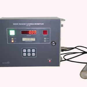
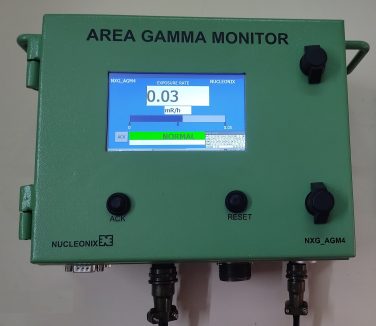
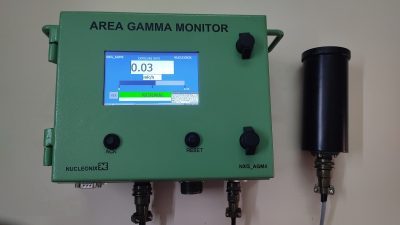
Area Gamma Monitor NXG_AGM4 indicates dose rate digitally on TFT display. There are a visual annunciator window GREEN & RED for NORMAL & ACTIVE conditions respectively, shown on TFT display. The entire screen flashes, when the dose rate alarm occurs and in normal condition the NORMAL window glows.
For NXG_AGM4, User interface is through Radgrid Software by using Ethernet Communication, Multiple Units can be networked.
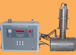
In Application that require External probe a Smart Probe is provided with RS485 interface. It can be installed in the measurement area, where as the display unit cab be in the Operations / Control Room.
Features
Specifications
| Radiation to be detected : | Gamma Radiation & X- Rays. |
|---|---|
| Range : | 0.01 -100 mR/hr 0.1 – 1mSv/hr 0- 50000 CPM Range and Unit are configurable. |
| Detector : | Energy compensated Halogen -quenched G. M. Tube GM131 – NXG_AGM4 or equivalent having a sensitivity of 7.5cps/mR/hr . |
| Energy Response : | +/-25% from 100keV upto 1.25MeV. |
| Accuracy : | +/- 10% Full scale with Cesium source. |
| EHT : | 400V to 700V DC adjustable (Typical 500V) (factory set). |
| Display : | 5”TFT is used for display of doserate, hardware status information & also for visualization of preset alarm and other parameters. |
| Overload : | Senses overload above 200% of fullscale and upto 1 R/ h & indicates on display “OFL”. |
| Over-range : | Senses if the radiation field being measured has exceeded the measurement range of the instrument and upto 200% of the instrument and displays “OVR”. |
| Time Constant : | First Stable reading on Power ON within 1 min. Normal (Slow) : 30 sec to 0.5 sec automatically varying inversely with the radiation level. |
| Abrupt detection : | Update the current reading within 2 sec. |
| Calibration Accuracy : | +/- 10% through out the range. |
| Alarm range : | 0.01 mR/Hr to 99.99mR/hr. 0.1µSv/Hr to 999µSv/hr. 1-50000 CPM . The alarm level setting will be carried out through Radgrid Software by Ethernet Communication. |
| Alarm Indication : | a) Red Mimic flashing large area on TFT display. b) Loud alternating audio tone (Dual frequency tone). |
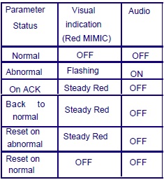
Alarm annunciation scheme
As tabulated below :
Instrument Controls :
a) Acknowledgement icon for muting audio alarm.
b) Reset icon for resetting the Alarm indication and alarm relay.
Instrument Fault indication :
HV failure : Visual alarm with flashing red MIMIC indication & “HV” message on display.
Detector failure :
Visual alarm with flashing red MIMIC & “Detector Failure” message on display. Fault indications shall be cleared automatically if normal status is resumed.
Detector Housing:
(In case of External Probe)
a. The Smart Probe is located external to the Display Unit.
b. It is housed in a suitable, air-tight SS shell with built-in pre-amplifier, HV & Microcontroller with RS485 interface.
c. The instrument is provided with 10mtr cable between Smart Probe and the monitor.
d. The detector housing qualifies industrial protection Class IP-54.
e. A separate mounting bracket for detector housing is provided.
External Console
RJ 45 connector for Ethernet port.
Computer Interface : The monitor has a Ethernet 10/100Mbps port for interfacing with a remote Windows PC. The features supported by Ethernet port are given below.
The PC and the NXG_AGM4 unit shall operate in a Client/ Server configuration and the software(RADGRID) protocol will be TCP.
The PC software shall give commands and send queries. The NXG_AGM4 unit will carry out various functions in response to the queries.
The firmware of the monitor shall be able to send the instrument data like instrument IP, instrument type, input range, display range, alarm settings, alarm status, current reading, diagnostic status of EHT/GM tube etc. to the Host PC on demand.
The firmware shall be able to receive commands from Host PC and carry out the setting of different parameters like instrument IP, instrument type, input range, display range, alarm settings, Ack, Reset, instrument address etc.
It can store data for every second. Last 60 Days data will be in store in the Instrument.
Input Power : 230V AC +/-10%.
Mechanical Enclosure:
Size: 180H x 178W x 38D.
Weight: 1Kg approx.