Continuous Air Monitor (Alpha / Beta) * [ TYPE : NXG_CAM4_AB ]
Technical Data

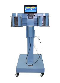
Continuous Air Monitor, Type: NXG_CAM4_AB manufactured by Nucleonix Systems, manufactured by Nucleonix Systems, is a dual scintillator based continuous air monitoring system, designed using state-of-art electronics and is primarily used for, simultaneously checking Alpha & Beta activity present in the form of suspended particulate in air. It is very much essential to monitor the quality of air in & around Radiochemical plants, reprocessing plants in disaster scenario and other strategic locations.
It essentially has an air suction system comprising of a suction pump, rotameter or digital flow meter to measure air flow rate, suction chamber with arrangement for trapping of suspended dust particulate onto the filter paper. A dual scintillator based detector assembly, facing the filter paper counts, Alpha and Beta particulate activity simultaneously in CPM /CPS/Bq on continuous basis.
Air-sampler detector assembly consists of a filter holder 60mm dia, a suction chamber with air inlet and outlet & detector housing fabricated with stainless steel .Alpha-Beta detector consists of ZnS(Ag) scintillator deposited on Plastic scintillator of 50mm diameter, coupled to matched PMT with Pre-amplifier. Detector efficiency achieved for Alpha is about 25% with Am241 and for Beta it is about 25% with Sr90 / Y90 and Collection efficiency obtained is better than 97% is achieved with this design. Suction chambers design facilitates the user to easily replace the filter paper periodically as per the requirement.
Electronic module: This will indicate, the air sample activity deposited on the filter paper in terms of CPM/ CPS/ Bq .Other built-in electronic sub-systems include HV module, SMPS, controller card, EMI/EMC filters, current loop circuit, relay & relay driver circuit, etc .Front panel has TFT display with touch screen, alarms indication on TFT display, audio buzzer, etc. Enclosure has connectors for connecting to Scintillation probe, 17 pin I/O connector, test sockets, Ethernet connector, A.C. mains switch, fuse holder etc. This module will provide alarm annunciation both visual and aural when the activity exceeds preset level. This system provides current loop output; relay output on 17 pin I/O connector. Ethernet port facilitates connection to NXG_RadGrid / SCADA for data communication for visualization of CAM parameters.
Features
Specifications
The electronic unit comprises of low voltage power supply, High voltage supply, Pre-amplifier & Amplifier, Count rate meter and Alarm generation module. The electronic unit and the detector assemblies are mounted inside a single floor mounted trolley.
AIR-SAMPLER CUM DETECTOR ASSEMBLY :
The air sampler cum detector assembly for alpha consists of a filter holder 60mm dia., a suction chamber with two nozzles (air inlet and outlet) of size ?? serrated and detector housing.
Air samplers are fabricated with stainless steel SS 304L. Air sampler is designed and fabricated to achieve the particle collection efficiency better than 97% for air particles down to 0.3 micron size on glass filter paper.
Dual scintillator based detector assembly measures simultaneously both alpha and beta activity present in a given sample separately. It uses ZnS(Ag) scintillator deposited on plastic scintillation material and coupled to a 2? PMT. To minimize the gamma background adequate lead collar / brace shielding has been provided.
PERFORMANCE WITH ALPHA SOURCE : Efficiency for alpha(Guaranteed): with calibrated Am241 standard source >25%.
Standard source used: Eckert and Ziegler make beta wide area reference source of activity 1.13KBq.
PERFORMANCE WITH BETA SOURCE : Efficiency for beta(Guaranteed): with calibrated Sr90 / Y90standard source >25%.
Standard source used: Eckert and Ziegler make alpha reference source of activity 1.020KBq.
Vacuum pump-motor set:
| Free air displacement : | Rated for 150 liters/min |
|---|---|
| Ultimate vacuum: | 200 mm Abs(22? Hg) |
| Pressure : | 1.4 Kgs/cm^2 (20 lbs). |
| Duty : | Continuous. |
| Electric Motor : | ? HP, 1440 RPM with gear box, 230V AC, capacitor start, single phase TEFC B-56 frame, Class ?B? insulation, continuous rating. |
| Vanes : | Made of self-lubricant special H17 grade graphite. |
| Bearings : | Sealed ball bearings. |
| Mountings : | Pump and motor mounting shall be on a common base plate. |
| Drive : | ?V? belt and pulley driven (belt covered by belt guard) |
| Air inlet/outlet : | ? serrated nozzles. |
| Vibration : | Suitable anti-vibration pad. |
| Cooling : | Air cooled. Very low noise pump, Audio noise @ 1metre is less then 50db. |
| Pump failure alarm : | Pump failure alarm indication is provided on the instrument and the same is also wired onto the remote console. |
| Make : | Gast Inc, USA. |
Count-rate meter :
The count rate measurements are carried out by the Data acquisition unit from the corresponding radiation type detected by the ZnS (Ag) scintillator detector. Important features of the count rate meter are listed below.
| Unit : | CPM / CPS / Bq |
|---|---|
| Ranges : | 0 – 50000 CPM (or) 0 2000 CPS (or) 0 – 50000 Bq, with provision for unit selection and range adjustment. |
| Time Constant : | Between 60 to 1 sec automatically varying inversely with count-rate through out the range. |
| Display : | Color TFT Display is used for display of count-rate and hardware status indication & for visualization of preset alarm and other parameters. |
| Display updating : | First reading on Power ON within 12 secs. |
| Normal (Slow): | 60 sec to 12 sec automatically varying inversely with the radiation level. |
| Time Constant: | 60 sec to 12 sec automatically varying inversely with the radiation level. |
| Abrupt detection : | Update the current reading within 1 sec and return to normal mode |
| Overload : | Senses overload above 200% of full scale indicates on display ?OL? |
| Over-range : | Senses if the radiation field being measured has exceeded the measurement range of the instrument and upto 200% of the instrument and displays ?OFl?. inject |
| Recorder output : | 4 to 20 mA, with 600 ohm load Recorder output stabilitya) Non-linearity : Max = 0.025% of Span b) Offset current (Io=4mA) : Max = 0.0005% of Span / C c) Span Error (Io=20mA) :Max = 0.005% of Span / C |
| Accuracy : | / – 5% Full scale. |
| Calibration Accuracy : | /- 5% through out the range |
Testing Facilities :
Provision to Feed a suitable pulse generator signal for simultaneously testing of Count Rate meter will be provided on the rear panel. Additionally a test pulse mode through software for checking count- rate meter will be provided .
Audio visual alarm system:
The instrument indicates Alarm status on the TFT display for Active and Normal conditions. Two sets alarm relays will be provided.
Alarm range: 1CPS/CPM/Bq to full scale reading
Alarm setting : The alarm level setting shall be carried out through RS-485 serial port with handheld configurator / PC with password protection.
Alarm Indication :
a) Red flashing large area window display on TFT display.
b) Loud audio tone (single / dual frequency tones).
c) Tri-color Tower LED for indication of alarms condition & fault.
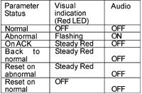
Alarm annunciation scheme
As tabulated below;

Instrument Controls :
a) Acknowledgement switch for muting audio
b Reset switch for resetting the Alarm indication and alarm relay.
c) Power ON/OFF switch with Power ON indication
Instrument Fault indication:
a) EHT failure: Visual alarm with flashing red LED indication & ?EHT? message on display
b) Detector failure: Visual alarm with flashing red LED & ?d-FL? message on display.
Remote /External Console:
a) 4 – 20 mA linear proportional to full scale display output. Current output will be able to drive load of 600 ohms. Output circuitry will be able to drive 200 mtrs. of twisted pair of wires.
b) Two sets of potential free contacts of Alarm relay (Change over). Contact rating 3 Amp at 250 VAC. The relay will be energized on normal condition and de-energised under alarm condition.
c) Remote alarm acknowledgement and reset signals for the field instruments.
d) Indication of instrument fault condition (detector, EHT & LV supplies failure), over range &
e) Overload conditions byupscale of 4-20 mA. (22.5 mA).
f)All these signals will be terminated on 17 pin sockets (Allied Connectors). The corresponding mating plug with5 mtr cable will be supplied with the monitor.
Computer Interface:
The monitor shall have a Ethernet 10/ 100 Mbps port for interfacing with a remote Windows. The features supported by Ethernet port are given below.
Self Diagnostics :
The monitor has built-in self diagnostics. On being powered it will perform tests to ensure that all components and sub systems are functioning properly. It will check for the Power supply, High Voltage Supply, Detector, Counting and measuring circuits, Alarm Systems and Display Systems.
The firmware is designed for high reliability and availability.
Test points are provided for checking the EHT voltage and for connecting external input pulse signals.
Input Power :
230VAC /-10%, 50Hz, single phase supply. Power ON/OFF indication will be provided with an indicator LED. Spike suppressor and line filter are provided.
Environment:
The instrument is designed to be able to withstand temperature up to 500 C and relative humidity upto 90% in radiation areas.
Environmental compliance :
As per IS 9000 Part III & IV
EMI / EMC compliance:
As per IEC 61000 / ANSI N42.17.


