


Description
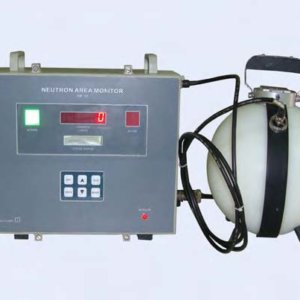
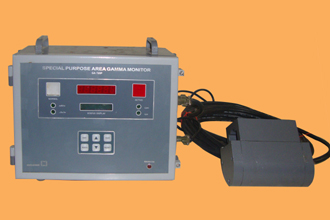
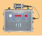
Area Gamma Monitor type GA 720S, manufactured by NUCLEONIX SYSTEMS employs based design and is primarily meant to serve as a Gamma Zone Monitor to indicate dose rates and give alarm, visual and aural, once the dose rates exceed the preset level fixed by the user. Also relays will be activated on alarm.
This unit will be useful for monitoring Gamma dose rate levels in working areas of various Radiological / Nuclear facilities which may include reactor building, Atomic power stations, Radiochemical / Reprocessing plants, waste immobilization plants & other similar facilities. This unit indicates the dose rate digitally on a 6 x 7 segment LED display. Each of the annunciator windows for NORMAL and ACTIVE conditions has LED array. Once alarm triggers ACTIVE window starts blinking.
Unit can be programmed / configured using front panel keypad which can be deactivated after completion of programming. Configuring the unit namely setting preset level, setting reset mode – AUTO/MANUAL etc are achieved by this keypad.
Unit also performs self-diagnostics for HV failure, pulse processing electronics failure and detectors failure on power up.
Alarm acknowledge and reset pins are provided on the circular I/O connector for remote acknowledge & reset.
Applications :
1. This Area monitor is recommended for unit in Radiological installation, Nuclear medicine departments, PET-CT centres, I-131 therapy wards, medical cyclotron facilities & Radiotherapy departments etc.
2. It is also recommended in Nuclear installations, waste immobilization plants Nuclear power plants & other similar Radiological installations.
Features


Specifications
| Radiation to be detected : | X -ray & Gamma Radiation |
|---|---|
| Range : | 1 mR/hr to 1000 R/hr in two ranges 1micro Sv/hr to 10000 micro Sv/hr. Unit is configurable Range selection is automatic. |
| Detector : | Energy compensated Halogen quenched G. M. Tube. GM131E |
| Energy Dependence : | Within +/- 18% of true dose rate from 100 keV to 1.33 MeV gamma rays |
| Accuracy : | +/ – 10% with Cs-137 |
| EHT : | 400V to 700V DC adjustable (Typical 500V) |
| Display : | Auto-ranging direct reading, 6 digit 7 segment LED display and 16×2 LCD display. 6 x 7 segment display is used for display of dose-rate information and hardware status information & 16×2 LCD display is used for visualization of preset alarm and other parameters. |
| Display Resolution : | 0.01mR/hr / 0.1 µSv/hr / 1 CPS / 1 CPM |
| Overload : | Senses overload above 200% of fullscale and upto 10000R/h & indicates on display “OL” |
| Over-range : | Senses if the radiation field being measured has exceeded the measurement range of the instrument and upto 200% of the instrument and displays “OFl”. |
| Recorder output : | 4-20 mA, with 600 ohm load. |
| Time Constant : | First reading on Power ON within 5 secs. Normal (Slow) : 15 sec to 1 sec automatically varying inversely with the radiation level (Count rate). Abrupt detection : Updates the current reading within 2 sec and returns to normal mode. |
| Calibration Accuracy : | +/- 10% through out the range. |
| Instrument “ON” Indication : | RED Neon indicating A.C. lamp |
| Alarm range : | 0.1 – 99.9 mR/hr OR 1 – 999 µSv/hr 1 – 50000 CPM OR 1 – 2000 CPS The alarm level setting can be set through front panel keypad or RS-485 Serial port using handheld configurator or PC provided with password protection. Front panel keypad is provided with DIP switch de-activation. |
Alarm annunciation scheme
As tabulated below :
Instrument Controls :
a) Acknowledgement icon for muting audio alarm.
b) Reset icon for resetting the Alarm indication and alarm relay.
c) Power ON/OFF switch (This is inside the cabinet) with Power ON indication
Instrument Fault indication :
a) EHT failure: Visual alarm with flashing RED LED indication & “Eht” message on display
b) Detector failure: Visual alarm with flashing red LED & “d-FL” message on display.
c) Microprocessor / microcontroller failure: Visual alarm with flashing green lamp.
d) Fault indications are cleared automatically if normal status is resumed.
Detector Housing:
a) The G. M. Detector will be located external to the Monitor.
b) It is housed in a suitable, air-tight SS shell with built-in pre-amplifier to drive upto 50 mtrs long cable. It complies to IP54 protection levels 20mm thick lead shielding for pipeline mounting is provided. SS straps for fixing the probe onto pipeline is provide.
Monitor Enclosure:
a) Vapor-tight, rugged & elegant.b) The door is provided with lock and key arrangement
c) The enclosure is designed to qualify minimum industrial protection Class IP-65.
d) Decorative with visual aesthetics, prominent alarm display and good readability.
Monitor Enclosure:
a) Vapor-tight, rugged & elegant.
b) The door is provided with lock and key arrangement
c) The enclosure is designed to qualify minimum industrial protection Class IP-65.
Mounting :
Detector housing is mounted using clamps on top of the monitor.
The monitor is wall mountable type. Brackets for the monitor & detector housing will be supplied along with the equipment.
Remote /External Console :
a) 4 – 20 mA linear proportional to full scale display output. Current output will be able to drive load of 600 ohms. Output circuitry will be able to drive 200 mtrs.of twisted pair of wires.
b) Two sets of potential free contacts of Alarm relay (Change over). Contact rating 3 Amp at 250 VAC. The relay is energized on normal condition and de-energised under alarm condition.
c) Remote alarm acknowledgement and reset signals for the field instruments (Normally open contact).
d) Indication of instrument fault condition (detector, EHT & LV supplies failure), overflow & overload condition by up-scale 4-20 mA. (22.5 mA).
e) All these signals are terminated on a 17 pin socket (Allied Connectors). The corresponding mating plug with 5 mtr cable will be supplied with the monitor.
f) RJ45 connector for Ethernet port
g) RS-485 serial port (optional). This is provided, on a pair of D-type connectors (male & female).
Computer Interface :
The monitor shall have a Ethernet 10/100 Mbps port for interfacing with a remote IBM PC-compatible computer.
The features supported by Ethernet port are given below.
The PC and the monitor shall operate in a host-slave configuration and the software protocol will be MODBUS/TCP.• The PC as the host shall give commands and send queries. The monitor will carry out various functions in response to the queries.
The firmware of the monitor shall be able to send the instrument data like instrument ID, instrument type, input range, display range, alarm settings, alarm status, current reading, diagnostic status of EHT/GM tube etc. to the Host PC on demand.
The firmware shall be able to receive commands from Host PC and carry out the setting of different parameters like instrument ID, instrument type, input range, display range, alarm settings, Ack, Reset, instrument address etc.c. The instrument is provided with 10 mtr cable between Smart Probe and themonitor.
RS485 (Optional)
This monitor has a RS-485 Serial Communication port for interfacing with a PC. The PC and the monitor operate in a host-slave configuration in a multi-drop network through this interface. The PC, as the host will give commands and send queries. The monitor will carry the various functions as per the required information in response to the queries.
The firmware of the monitor sends the instrument data like Instrument ID, Instrument type, Input range, Display range, alarm settings, alarm status, current reading, diagnostic status of EHT/GM tube etc. to the Host PC on demand. The firmware receives commands from Host PC and carries out the setting of different parameters like Instrument ID, Instrument type, Input range, Display range, alarm settings, Ack, Reset, EHT setting, Instrument address etc. The configuration settings are password protected and the password is user defined.
The detailed specifications for the interface are as follows:-
Type : RS-485 Multi-drop Serial Communication Port, Half Duplex Bi-directional communication.
Character Format : ASCII
Protocol : Modbus/RTU
Bit Rate : User configurable to 9600 or 19200 bits per sec.
Address : User configurable from 0 to 255.
Connector : 9-pin D-type connectors (2 connectors connected in parallel for daisy chaining a number of instruments). The mating connectors with cover are supplied.
Self Diagnostics :
The monitor will have built-in self diagnostics. On being powered it will perform tests to ensure that all components and sub systems are functioning properly. It will check for the Power supply, High Voltage Supply, Detector and pulse processing electronics.
Input Power :
230VAC +/-10%, 50Hz, single phase supply. Power ON/OFF switch will be provided with a neon indicator. Spike suppressor and line filter are also provided.
Environment :
The instrument will be able to withstand temperature upto 50o C and relative humidity upto 90% in radiation areas.
Environmental compliance :
As per IS 9000 / ANSI N 42.17
The instrument enclosure and detector assembly are IP-54 compliant. Electronic unit will withstand cumulative radiation dose of 10000 Rad. (30 years of operation).
EMI / EMC compliance:
As per IEC 61000 / ANSI N42.17
Mechanical Enclosure:
Size : 357H x 380W x 140D, Weight : 8.5kg approx