


Description
Features
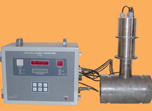
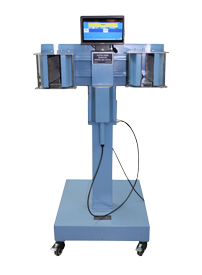
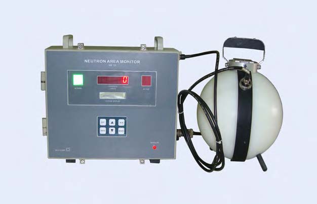
Neutron Area Monitor NM729 manufactured by Nucleonix Systems designed using advanced technologies is primarly meant for detecting neutron flux leakages and measure dose rate in reprocessing plants, atomic power plants accelerator buildings, cement factories and medical cyclotron facilities. It serves as a neutron zone monitor to indicate flux / count rate or dose rate and gives alarms visual / aural once the preset levels fixed by the user exceeds. Also relays will be activated.
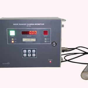
This unit indicates the dose rate digitally on a 4 x 7 segment LED display / TFT display. Each of the annunciator windows for NORMAL and ACTIVE conditions has LED array. Once alarm triggers ACTIVE window starts blinking.
Unit can be programmed/configured using front panel keypad which can be deactivated after completion programming. Configuring the unit namely setting preset level, setting reset mode -AUTO/MANUAL etc are achieved by this keypad. Unit also performs self-diagnostics for HV failure, pulse processing electronics failure & detectors failure on power up.
Alarm acknowledge and reset pins are provided on the circular I/O connector for remote acknowledge & reset. Ethernet RS485 port is also available optionally.
STANDARD SPECIFICATIONS
| 1. Radiation detected | Neutron Flux. |
|---|---|
| 2. Detector Type | He3 neutron Proportional detector. |
| 3. Gas pressure | 1520 (torr). |
| 4. Cathode Material | SS |
| 5. Operating voltage | 1000V +/- 900V. |
| 6. Sensitivity | 30CPM per Rem/hr with Am-241-Be (Typical). |
| 7. Detector assembly | Surrounded by 9” dia polyethylene moderator. |
| 8. Energy Response | Thermal Energy to 10MeV within +/-10% with respect to Am-Be. |
| 9. Range of measurement | (0-10)mSv/hr. |
| 10. Time constant | Inversely varying with count rate. |
| 11. Display | TFT / 6 digit 7 segment LED display for display of neutron flux 16×2 LCD display for visualization of preset alarm & other parameters. |
| 12. Time Constant | 16 sec to 0.5 sec inversely varying with count rate. |
| 13. Alarm range | Available throughout the range. |
| 14. Alarm System : | a. Alarm will be indicated by Red (LED) flashing large area window display and Loud audio alarm. b. Distinctive EHT / Detector failure alarm. c. Large area instrument “ON” indication. d. Provision for display of alarm set point. e. Alarm set – point will be adjustable continuously. f. The instrument will have alarm acknowledgement and Reset switches. g. Provision for remote alarm acknowledge and reset. |
| 15. Monitor Enclosure : | Vapour-tight, rugged & elegant. The door shall be lockable with knob. The instrument can be offered with compliance to required IP standards. |
| 16. Remote/External console : | a. 4-20 mA full-scale output. Output circuitry shall be able to drive 200 mtrs. of twisted pair of wires. b. Two sets of potential free contacts of Alarm relay (Change over). Contact rating 3 Amps at 250 VAC. c. Remote alarm acknowledgement and reset signals for the field instruments. |
| 17. Self-Diagnostics : | The monitor will have built-in selfdiagnostics.On being powered it will perform tests to ensure that all components and sub systems are functioning properly. It will check for the High voltage supply, Detector and pulse processing electronics. |
| 18. Power : | 230 VAC +/-10%, 50 Hz, single-phase supply. Line filter with transient suppressor is built-in. |
| 19. Environment : | The instrument will be able to withstand temperature upto 500C and relative humidity upto 90% in radiation areas. |
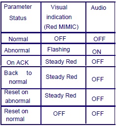
Alarm annunciation scheme
As tabulated below :
OPTIONAL (AT EXTRA COST)
1. Computer Interface:
The monitor will have a RS-485 Serial Communication port for interfacing with a PC. The PC and the monitor will operate in a hostslave configuration in a multi drop network through this interface.
The PC, as the host will give commands and send queries. The monitor will carry out the various functions as per the required information in response to the queries.
The firmware of the monitor will be able to send the instrument data like instrument ID, Instrument type, input range, display range, alarm settings, alarm data, current reading etc to the Host PC and carry out the setting of different parameters like instrument ID, Instrument type, input range, display range, alarm settings etc. The user will provide detailed list of the command and response for the Host-slave communication.
The detailed specifications for the interface will be as follows :
Type : RS-485 Multi drop Serial Communication Port, Half-duplex bi – directional communication
Protocol : MODBUS RTU
Bit Rate : Baud rate will be 19,200 by default. VB software & configurator will be able to communicate at these baud rates. For operating at other baud rates PC will modify the baud rate settings of the Area Monitor.
Address : User configurable from 0 to 255. Device address is to be entered using PC. Address range is 0-255. Each of the units should have distinct address. This address is stored in EEPROM and whenever an address command is received from central console, if address matches to this monitor, it will respond to the queries.
Connector : 9 pin D-type connector.
2. EMI / EMC Compliance :
Unit can be offered with EMI/EMC complaince on request at extra cost.
3. IEC Enclosure Standard :
The instrument can be offered with complaince to required IP standards.