


Description
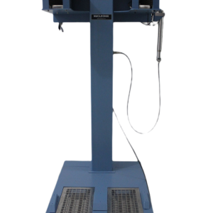
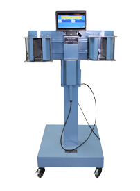
Portal Monitor PM735P developed and manufactured by Nucleonix Systems is designed to monitor Beta-Gamma contamination of whole body of radiation workers in a Nuclear facility. It uses state of art electronics, based on ARM series SBC. It is highly reliable, rugged and durable in construction.
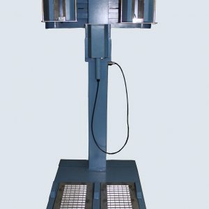
Its unique configuration facilitates fast whole body monitoring. Detectors placement and monitor mechanical construction allows person to check for contamination easily. This is a side entry portal, allowing monitoring of front and back of the person simultaneously.
The Instrument has powerful diagnostic facilities to check for various functions like EHT failure check, Detector Check, High background check, pulse processing failure check for faulty channel identification for trouble shooting and repairs. Detector probe comprises of detector and pulse shaping circuit. The o/p of the probes will be TTL and it will draw LV from the Electronic Unit. HV to all the probes will be common. The portal monitor will activate relay contacts on alarm. The portal monitor has Ethernet port for communication with a remote host PC.
Features
- * Whole body portal monitor designed to monitor Beta Gamma contamination uses state of art electronics design.
- * Uses ARM processor based SBC with embedded code, serial bus based devices makes equipment electronics compact and highly reliable.
- * Comprises of 21 monitoring channels comprising of large area plastic scintillation detector assemblies.
- * User I/O interface is through a detachable keyboard and large TFT monitor.
- * Alarms and other status information is indicated on the LED mimic & corresponding status LEDs.
- * Built-in serial port provided facilitates networking for centralized monitoring and diagnostics.
- * Monitor is designed to withstand the harsh atmospheric conditions in Radiochemical plants.
Specifications
| DETECTOR ASSEMBLIES : | a) 250 x 350mm for body: 10 Channels (Front & Back facing) b) 300x300mm for body – 4 Channel (Upper& Lower leg) c) 300x300mm for head – 1 Channel. d) 350 x 150mm for foot – 2 Channels e) 220 x 140mm for hands – 4 Channels |
|---|---|
| Overall Efficiency : | Greater than 20% with Sr-90 + yt 90 on the detector surface. |
| Channels | 21 channels in all, covering entire body from head to foot on each side of the person.4 Channel are additionally provided for checking with hands. |
| BACKGROUND: | System periodically checks for detector background & updates it, which is stored in the Memory. Background Counts are automatically subtracted while contamination of personnel is monitored. During background check, if high background or low background is sensed, instrument will halt ready status and show appropriate messages and continue to update background till recovery. |
| PERSON SENSING: | A person standing inside the portal is automatically sensed by IR source detector combination. |
| COUNTING SEQUENCE: | Once a person stands inside the portal monitor and activates the IR optical sensors the counting sequence is initiated and ‘COUNTING ON’ LED is activated. Counting with automatic background subtraction goes on for 5 sec (or for the preset time set by Health Physicist) and contamination status is reported visually. |
| SHIELDING: | Suitable lead shielding for all the channels to minimize background radiation. |
| AUDIO / VISUAL INDICATIONS & ALARMS : | Refer to table 1. |
| DISPLAY : | 10.1” TFT color display for showing user friendly messages, for guidance during monitoring and for mimic indications and it can easily rotate to adjust view point. |
| KEYPAD: | A detachable keypad has been provided for the health physicist to be able to set and configure the Portal Monitor. |
| MIMIC: | A human picture which indicates region of contamination has been provided on the TFT monitor |
| USER GUIDANCE: | Suitable user guidance audio / visual messages are generated during monitoring in English. Alternate languages may be supported on request. |
| ALARM LEVELS: | Each counter channel can count upto 9999 counts. So alarm level can be set for each channel between 0 to 9999 counts. Other units selectable are CPS & CPM. |
| SYSTEM SETTINGS: | Background counting : 1-99 seconds, Personal monitoring time counting time : 1 – 99 seconds, Alarm range : 0-9999 CPS/CPM/Counts, Background low limit : 0-9999 CPS/CPM/ Counts, Background high limit : 0-9999 CPS/CPM/ Counts. |
| BYPASS FAULTY: | : All detector signals are independently counted. This allows any faulty detector channel to be bypassed and system usage can be resumed. |
| SELF DIAGNOSTICS: | It performs diagnostic check at power-up and also on user prompt to check for various parameters of the instrument. Self check can be done by the user using hand-held keypad. The various checks that are performed are EHT check, detector check, Pulse processing electronics check for faulty channel identification and high background check.. |
| RELAY CONTACTS : | Alarm Change Over Contacts – 2 sets for clean condition for turnstile operation. |
| TEST FACILITIES: | Provision for performing test background, test acquire directly through keypad. |
| DATA STORAGE : | Automatic storage of alarm data along with time stamp for upto 50 readings.t extra cost. |
| DETECTOR ARRANGEMENT : | All detectors are clamped and mounted on frames for easy removal during maintenance. |
| FRONT, BACK & TOP DETECTOR ASSEMBLIES : | Lead shielding of 12 mm will be used. |
| FOOT DETECTOR ASSEMBLY : | Two detachable SS trays with detector assemblies mounted on them are used for left and right foot. Both the assemblies are covered with SS grill. Detectors are shielded with a ½” thick lead. Detector assemblies have easy lift and remove arrangement. An additional SS cover is also provided for entire foot assembly to hold body bottom structure to prevent contamination. |
| OPERATING ENVIRONMENT : | Upto 50oC, RH 95%, continuous operation |
| MECHANICAL SPECIFICATIONS | MATERIAL: Entire portal monitor material is made of SS including SS honey comb mesh and inside structural support frame is made of MS with power coating. DIMENSIONS: SS frame of below dimensions Inner (approx) 6’ 6” X 1’ 9” X 4’ 3”. Other mechanical details: Each detector assembly has Honey comb mesh,except for foot assemblies. Foot dust tray, provided facilitates easy removal for cleaning of dust. Height adjustment is provided for Head detector assembly. |
| S.No | Function | Indicator | Color of Indicator | Status Steady / Flash |
| 1 | Monitor in Progress | Busy | Green | Steady |
| 2 | No Contamination | Clean | Green | Steady |
| 3 | Contamination Detector | Contamination | Red | Flash |
| 4 | High Background | High BG | Amber | Steady |
| 5 | Incomplete Operation | Incomplete | Yellow | Steady |
| 6 | Instrument Ready | Ready | Amber | Steady |